PIC microcontrollers are a family of specialized microcontroller chips produced by Microchip Technology in Chandler, Arizona. The acronym PIC stands for “peripheral interface controller,” although that term is rarely used nowadays.
The reason I got into PICs was to experience a low-level world of make it from absolute scratch. If any of the following apply to you, then you should definitely give it a go:
You want to be able to build embedded projects for very little cost.
You are interested in learning the inner-workings of a microcontroller.
You find it satisfying to build something from scratch.
When starting with PICs its a good idea to get one, you can get these from microchip.com or I got my first one and a few others from a local tech store. Alongside a PIC you should also get a programmer, the one I got is the PICkit3.5 which is a slightly improved clone over the original PICkit3, I got it from here: long-link. And with that finally I would recommend a few dupont wires and a power source of 5 volts.
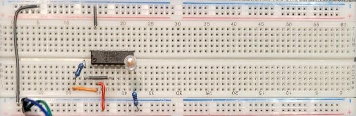
Once you have received all the items and put it all together as per the guide I have a few debugs to address:
supply enough current! the average PIC accepts about 2 – 5 volts, if you aren’t sure about your PIC it is easy to find in the data sheet as all you need to do is search for operational voltage and the range should be there.
unlike arduino PICs output ground, this is a problem because if you stick a diode on the wrong way it isn’t going to work so keep this in mind.
side view of circuitfull view of circuitwiringworking view
And that concludes my starting with PICs, Next I hope to create a servo-setter for my dad as he constantly requires me to re-program my arduino for the servo setting.
We are using ardupilot because we saw a youtuber by the name of rctestflight using it and it looked like it worked well(and it does).
In order to edit the ardupilot config access this file /etc/default/ardupilot also other settings are changeable in the file here: (for example console should be linked with the GCS’s (Ground Control Station’s) ip address) http://ardupilot.org/plane/docs/parameters.html?highlight=parameters
Also, keep in mind that in order to connect with GCS the beaglebone blue will need wifi do this through the connmanctl. A problem sometimes is that the wifi is disconnecting I fixed this by connecting my own antena.
This file exists just in case you need to change some settings: /usr/bin/ardupilot/aphw
Lines 5 to 7 of the file switch on power to the BBBlue’s +5V servo rail – i.e. for when you’re using servos. Not necessary for ESCs.
sudo systemctl disable <name of service>
sudo systemctl start <name of service>
sudo systemctl stop <name of service>
Just in case the ArduPilot parameter settings files: /var/APM/{ArduCopter.stg,ArduPlane.stg,APMrover2.stg,AntennaTracker.stg}
I start my ardupilot through a .sh file, all it does is it calls the executable with the right parameters, this is where you should change the ip. ardupilot.sh
If you’re having difficulty establishing a link, look at the following:
Ensure you’ve opened the necessary ports in the GCS computer’s firewall. Perhaps even disable the firewall temporarily.
Be absolutely certain of the GCS computer’s IP address, because if you happen to be ‘dualing’ Windows and Linux on the same machine, routers will sometimes assign different IPs to each of the OSes.
If you’re getting a ‘port is already open’-type error, turn off the GCS software’s auto-connect feature, restart the program, and try again manually.
Remember that a server set to listen on the loopback address (127.0.0.1) won’t see external nodes on your network.
To make sure you are doing it right this is my setup of connections also I am using the em-506 GPS and a simple reciever with ppm connected to the 3v3 and gnd and the sbus pins on the bbb like so:
After that open your GCS’s software and it should automatically connect with your computer. When I first started up the software I needed to calibrate some of the beaglebone’s sensors so if there are any difficulties consider re-calibrating the sensors.
You can re-calibrate by going onto your GCS: mine is QGroundControl; click on the top left icon, click on your sensor. and then follow the prompts to re calibrate.
1. click on icon
2. click vehicle setup
3. click sensors
4. choose
this is the accelerometer calibration as an example
I have also added this command: sudo ./ardurover -C /dev/ttyO1 -A udp:192.168.0.191:14550 -B /dev/ttyO2 -F /dev/ttyO5
To run on startup because the services aren’t working for some reason: you can edit it with this: sudo crontab -e
Oh and this command aswell to power the power-rails: ./usr/bin/ardupilot/aphw
At the end all I need to run ardupilot is to ssh to my bbb and then run the ./ardupilot.sh script.
If all works in the end you should end up with a red flashing led on your bbb and a neat looking ardupilot GCS.
To configurate the settings on theBLHeli_s you need a flashing tool, the one I used is the Arduino Mega 2560 and it seems to be the only one that works. You also need a computer and a cable to connect the flashing tool to your computer and two male to male wires.
Here are the steps you need to take to flash your esc:
Extract the zip file into your downloads(it doesn’t matter where).
Run the executable BLHeliSuite.exe as administrator.
Now go to the make interfaces tab and select Arduino mega 2560(depending on your Arduino).
Make sure your com port is connected up to the Arduino mega and click Arduino 4way-interface you should see some messages, click ok.
Now connect the ground wire of the esc to the ground output of the Arduino mega with one of the male to male wires and connect the other input to pin 51 on the Arduino mega. Make sure you chose pin 51.
Now connect the esc to a battery, Make sure the ESC isn’t connected to the motor(I am pretty sure that delayed me for a while). Also make sure none of the wires are shorted.
Go to “Select ATMEL / SILABS interface” and select the SILABS BLHeli Bootloader (4way-if).
Then go to SILABS ESC Setup and select the right com port.
Then press connect and wait you might see a message on your screen, click ok.
Then press read setup it should say ESC#1 Setup Read Successfully.
Then change the settings to your desire and press write setup it should say “Write ok”.